
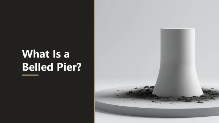
Ever seen a foundation shaft that flares out like a trumpet at the bottom? That cone-shaped base has a name and a job. A belled pier spreads heavy loads onto firm soil without widening the whole shaft.
A belled pier is a drilled shaft, also called an underreamed drilled shaft or caisson, with an enlarged cone-shaped base. Per the 1999 FHWA drilled-shaft manual, the bell gives greater bearing resistance than a plain shaft, stays within three times the shaft diameter, and suits cohesive soils that stand open.
What a Belled Pier Actually Is
A belled pier is a drilled shaft with a wider base formed by an underreaming tool. The 1999 FHWA drilled-shaft manual describes an underream, or bell, cut after the shaft reaches full depth to give “greater bearing resistance than would be available with a cylindrical shaft.”
The same foundation goes by several names. A continuing-education course by Omar Alsamman, P.E. (CED Engineering course G01-002) notes that drilled shafts are also called bored piles, cast-in-situ piles, drilled piers, and caissons. So a belled caisson and an underreamed drilled shaft are the same idea.
The bell is shaped by a belling bucket. The CED course explains that the bucket goes down with its arms closed, then opens and rotates to carve the flared base. You can estimate the concrete for that shape with the belled pier concrete calculator once an engineer sets the sizes.
Why the Base Is Belled for More Bearing
The base is belled so the pier carries more end bearing without a wider, costlier shaft. The narrow shaft is cheap to drill, while the flared base spreads the load over a larger area of firm soil below it.
Per the 1999 FHWA manual, the bell diameter is “not more than three times the diameter of the shaft.” That cap limits how far the base can flare. Base resistance is assigned in compression loading, and for a belled shaft the end bearing on the bell does the work.
There is a trade-off the sources flag. The CED course notes that full base capacity needs large settlement. A belled pier is an end-bearing choice, not a free bonus. The table below sets out what each source states.
| Feature | What the source says | Source and edition |
|---|---|---|
| Bell diameter cap | Not more than three times the shaft diameter | FHWA 1999 manual (FHWA-IF-99-025); CED course G01-002 |
| Bell side angle | 60 or 45 degrees from the horizontal | FHWA 1999 manual; IBC 2021 Section 1810.3.9.5 |
| Soil suitability | Cohesive soils that stand open; not recommended in non-cohesive soils | FHWA 1999 manual |
| Bridge foundations | Do not use belled shafts for bridge foundations | TxDOT Geotechnical Manual |
| Reinforcement | The bell outside the central shaft is normally not reinforced | FHWA 1999 manual |
Bell Angle: 60 or 45 Degrees From Horizontal
Bell sides are cut at either 60 or 45 degrees measured from the horizontal, not from the vertical. The 1999 FHWA manual states that drilling buckets cut 60-degree underreams, where the sides make an angle of 60 degrees with the horizontal, and 45-degree underreams.
The CED course confirms the same convention, saying the bell is commonly angled 45 or 60 degrees to the horizontal. The angle comes from the tool and the design, not from a volume estimate. Stating it from the horizontal avoids confusion, since a steep 60-degree bell has nearly vertical sides.
Code treats this angle as a threshold. IBC 2021 Section 1810.3.9.5, titled “Belled Drilled Shafts” and read here as reproduced in the Illinois Building Code on UpCodes, requires the bell edge to meet the footing-edge thickness rule. For bell slopes under 60 degrees from the horizontal, vertical shear is checked. Confirm your own adopted edition, since numbers can differ.
Which Soils Suit a Belled Pier
Belled piers suit stiff cohesive soils that stand open while the bell is cut and cleaned. The 1999 FHWA manual lists homogeneous stiff clay, hardpan, or soft cohesive rock at shallow depth as places where a bell is easily constructed.
Loose, sandy ground is a different story. The FHWA manual states plainly that “bells are not recommended to be installed in non-cohesive soils,” and adds that belled shafts should not ordinarily be used where the bell would sit in cohesionless soil because of construction difficulties. A bell can collapse during cutting in such ground.
Agencies also set their own limits. The TxDOT Geotechnical Manual directs that, for its bridge work, belled shafts are not used for bridge foundations. Keep that narrow: it is one state DOT’s bridge policy, separate from the FHWA guidance on cohesive versus non-cohesive soils. Both point the same way for soft, caving ground.
Sizing the Pier Concrete, Not the Design
The calculator sizes the concrete for the pier you describe, not the pier itself. It adds the shaft cylinder, the bell frustum, and the toe, then applies waste. It does not check the 3x cap, the bell angle, or any bearing capacity.
Take the tool’s default pier: a 12-inch shaft 8 feet deep, a 30-inch bell 18 inches high, and a 6-inch toe, with 10 percent waste. Here is the hand-checked arithmetic.
- Shaft. pi x (0.5 ft)squared x 8 ft = 6.28 cubic feet.
- Bell frustum. (1.5 ft / 3) x pi x (1.25squared + 1.25 x 0.5 + 0.5squared) = 3.83 cubic feet.
- Toe. pi x (1.25 ft)squared x 0.5 ft = 2.45 cubic feet.
- Total. 6.28 + 3.83 + 2.45 = 12.57 cubic feet per pier; with 10 percent waste, 13.82 cubic feet, or 0.51 cubic yard.
One check worth noting as arithmetic: this bell is 30 divided by 12, or 2.5 times the shaft diameter, inside the FHWA 3x cap. The tool does not verify that for you. Bell size, bearing, and reinforcement come from a geotechnical report and a structural engineer, much like deciding how deep footings go.
Once an engineer sets the shaft, bell, and toe, use the concrete bell pier volume estimator to plan the pour. For related shapes, see the foundations and footings calculators.
FAQs About Belled Piers
What is a belled pier?
A belled pier is a drilled shaft with an enlarged, cone-shaped base called a bell or underream. Per the 1999 FHWA manual, the bell gives greater bearing resistance than a plain cylindrical shaft of the same diameter.
Why is the base of a pier belled?
The base is belled to spread the load onto more soil and gain end bearing without a wider shaft. The 1999 FHWA manual describes the underream as a way to achieve greater bearing resistance than a cylindrical shaft.
How big can the bell be?
Per the 1999 FHWA drilled-shaft manual, the bell diameter is not more than three times the shaft diameter. The current edition is GEC 10 (FHWA-NHI-10-016), which was not read here, so check it for any changes.
What angle are the bell sides?
Bell sides are cut at 60 or 45 degrees from the horizontal, per the 1999 FHWA manual and the CED course. A 60-degree bell has steeper sides than a 45-degree one. The angle is set from the horizontal.
What soils suit a belled pier?
Stiff cohesive soils that stand open, such as stiff clay or hardpan, suit a belled pier. The 1999 FHWA manual says bells are not recommended in non-cohesive soils, because loose sand can collapse while the bell is cut.
Are belled piers used for bridges?
The TxDOT Geotechnical Manual states, for its bridge work, do not use belled shafts for bridge foundations. That is one state DOT’s bridge policy. Your own geotechnical report and local code decide what is allowed.
Does the calculator design the pier?
No. The concrete bell pier calculator estimates concrete volume for the shaft, bell, and toe you enter. It does not check the three-times cap, the bell angle, or bearing. Size, bearing, and reinforcement come from an engineer.
Sources and Further Reading
References Used in This Article
- FHWA, Drilled Shafts: Construction Procedures and Design Methods, FHWA-IF-99-025 (1999); read on a third-party host; current edition is GEC 10, accessed 2026-10-21.
- Omar Alsamman, P.E., Construction and Behavior of Drilled Shafts (CED Engineering course G01-002), accessed 2026-10-21.
- IBC 2021 Section 1810.3.9.5, Belled Drilled Shafts, as reproduced in the Illinois Building Code 2021 (UpCodes), accessed 2026-10-21.
- TxDOT Geotechnical Manual (LRFD), Section 5: Drilled Shafts, Belled Shafts, accessed 2026-10-21.
A belled pier is engineered foundation work, so its size, bearing and reinforcement come from a geotechnical report and an engineer, not from a volume estimate. FHWA figures here are from the 1999 manual, and the current edition is GEC 10. Reviewed for accuracy by Prof. Dr. Khalil Mudassar, PhD. Last updated 2026-10-21.

Shakeel Muzaffar is the Founder and Editor-in-Chief, with over 15 years of experience in digital publishing and online tool development. He oversees editorial quality and formula verification to ensure accurate, practical, and easy-to-use calculators.